| Nous
allons réaliser une porsche 550 (la même que BILL) vu que
c'est un modèle relativement simple. J'en avait fait une il y a
1 an : |
We
are going to make a 550 Porsche ( the same as BILL) since it's a faily
easy model. I had done one a year ago |
(cliquez l'image pour agrandir)
|
| mais ayant effacé
le .blend, je part comme vous de zéro. Allez, attachez vos ceintures... |
but having deleted
the .blend, I am starting from scratch like everyone else. So, fasten your
seat belts.... |
-Téléchargez
le plan de la bête ici :
porsche_550.jpg |
-Download the beast's blueprint
here :
blueprints/cars_sports/porsche_550.jpg |
-Dans le Menu View, sélectionner
Background image, charger l'image et mettre le size sur 20. |
-In the View Menu, select
Background Image, load the blueprint and set size to 20. |
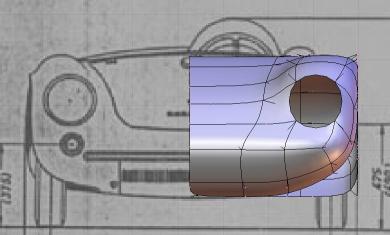
-Dans la fenêtre 3D,
mettre le curseur sur le centre de la roue avant gauche en étant
en vue de face (Numpad 1) et Add , Mesh , Circle et choisir 8 vertices.
Puis en se mettant en vue de dessus (Numpad 7) déplacer le cercle
vers le bas pour qu'il coincide avec le bord d'aile (humour) de la vue
de dessus. |
-In the 3D window, put the
cursor at the center of the left forward tire in Front View [Numpad 1]
and Add>Mesh>Circle. Choose 8 vertices. Next in Top View [Numpad 7] move
the circle down until it matches the edge of the wing. |
-En edit mode et vue 1,
supprimer le vertex du bas ("X") et positionner les autres pour correspondre
avec le passage de roue (en ayant activé les subsurfs sur 2 ou 3). |
-In Edit mode and in Front
view [Numpad 1], delete the lowest vertex [X] and move the other to match
the shape of the car around the tire (have the subsurf set to 2 or 3]. |
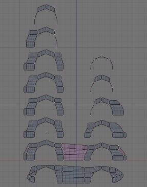
-Extruder les vertices comme
sur l'image 1, |
-Extrude the selected vertices
like on the picture, |
(cliquez l'image pour
agrandir)
|
| faire de même pour
la roue arrière et joindre le tout. Déplacer quelques vertices
pour coller au plan. |
Proceed the same way for
the zone around the back tire and join the two of them. Move a few vertices
to conform to the blueprint. |
-Sélectionner tous
les vertices du dessus en partant du bas de caisse et extruder 2 fois sur
l'axe y jusqu'au centre. Mettre le curseur sur un des derniers vertices
(Shift S). |
-Select all the above vertices
from the lower part of the car and extrude 2 times on the Y axis up to
the center. Put the cursor on one of the last vertices and press [Shift+S]. |
-On va faire une symétrie
en sélectionnant tous les vertices par la touche "A" , puis on les
duplique par Shift D , touche "M" et choisir "Local Z" , 2 fois "A" pour
tout sélectionner, puis "W" et "choisir remove double" , et enfin
Ctrl N si besoin. |
-We are going to make a
symetry by selecting all vertices with the A key, duplicating them with
[Shift+D], press M key and choose "Local Z". After that, press twice the
A key in order to select everything, W key and choose "remove double" and
last [Ctrl+N] if you see some faces improperly oriented. |
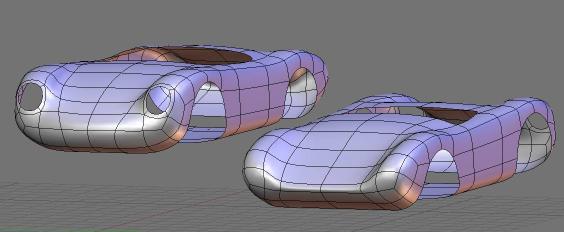
-Voilà vous avez
déjà une modélisation grossière qui nous servira
de base : |
-There you have a crude
model which is going to serve as the base for our more complexe work: |
(cliquez l'image pour agrandir)
|
Reprenons notre modèle
:
-Coupez la partie droite
que nous venions de créer par symétrie pour continuer la
modélisation (la visualisation globale du modèle par symétrie
est
faire régulièrement) : touche "B" pour slectionner
et "X". |
Let's go back to our model:
-Cut and detach the right
part that we just had created by symetry. We are going to work on a half
part (Do not forget to visualise regularly the complete model with the
symetry). Press the B key to select the part and X key to delete it. |
-Sélectionner la
face de l'emplacement du phare pour la supprimer, déplacer quelque
vertices pour arrondir les formes. Faire un Cut (touche "K" puis "Face
Loop Cut") et dplacer l'ensemble vers le phare. Les faces reprsentant
le capot sont ainsi descendues et alignées suivant le plan . |
-Select the face where the
forward light is supposed to be and delete it with X key. Move vertices
to give the car a more rounded shape. Make a cut (K key then "Face Loop")
and move the resulting edge toward the light. Faces representing the hood
of the car need to be lowered according to the lines on the blueprint. |
(cliquez l'image pour agrandir)
|
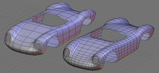
-Mettre les Subsurfs en
optimal pour mieux apprécier les formes, déplacer au mieux
les vertices pour coller au plan. Se mettre en vue de face (dans notre
cas Ctrl "3"), dplacer le modèle (pour coller au plan) puis placer
le phare et arrondir le bas de caisse |
-Turn on the Optimal option
for the subsurf to have a better perception of the general shape of the
car. Move vertices to replicate at best the blueprint. Go into Front view
(here Ctrl+3) and move the model(to have overlapping the blueprint) then
place the forward light and keep on rouding the lower part of the car according
to the image. |
(cliquez l'image pour agrandir)
|
-Faire une symétrie
et en vue de dessus (touche "7") faire l'arrondi de l'avant en déplaant
les 6 vertices centraux. |
-Make a symetry in Top view
(Numpad 7) and the rounding of the forward part of the car by tweaking
the 6 central vertices. |
-Recouper la partie droite
et faire la mme chose sur l'arrière : un cut dans le milieu qu'on
déplace vers l'extérieur et on aligne le coffre
la courbe
dessinée en pointillé sur le plan . |
-Cut off again the right
part et make the same thing for the backward part of the car: a cut in
the middle that you are going to move toward the edge of the car and set
the line over the doted one representing the trunk on the blueprint . |
(cliquez l'image pour agrandir)
|
-Il est important de se
documenter de photos du modèle, les plans ne suffisent pas pour
juger des formes. Sans ajouter de vertices déplacer légèrement
quelques vertices pour coller au mieux au modèle réel. |
-It is very important to
find pictures of the model because blueprints, in most cases, don't suffice
in order to judge shapes of a car. Without adding anymore vertex, move
slightly a few of them to better match the real model. |
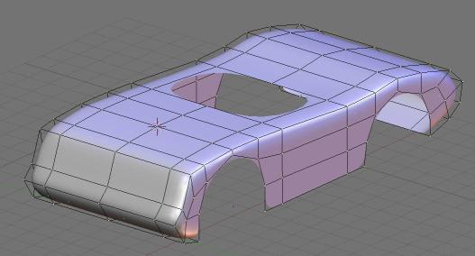
-En s'aidant des images
trouvées sur le net, la carrosserie prend forme. Il est important
de prévoir les découpes du capot et des portières
en plaçant les edges suivant le plan. On extrude et on scale ("E"
puis "S") les phares avant et arrières ainsi que l'habitacle. 1
coup de cut au niveau des portières et notre modèle est prêt
à être "figé". |
-With the help of pictures
found over the Internet, the car is shaping up nicely. Your main concern
here is planning: you must plan cutting out the hood, the trunk and the
doors by correctly placing the edges in regard of the blueprint.. Extrude
(E key) and Scale (S key) the forward and backwards lights and the sitting
compartment. Make a cut where the doors are supposed to be and our model
is ready to be converted.. |
-Le modèle actuel
est volontairement très léger en vertices pour pouvoir facilement
modéliser les arrondis. Pour les découpes, on a besoin d'un
mesh avec plus de maintien. Nous allons donc transformer notre mesh en...
mesh! |
-Our current model is purposedly
light in order to easily model the rounded shapes. For the cut out of doors,
trunk and hood however we need more vertices. We are going to transforme
our mesh into a... mesh! |
-Mettre le niveau de subsurf
sur 1, et faire Alt "C". conserver le modèle original dans un calque.
mettre le nouveau modèle en subsurf . |
-Set the subsurf level to
1 and press [Alt+C]. Keep the original model on another layer and turn
on subsurf on the new model. |
(cliquez l'image pour agrandir)
|
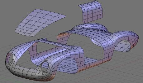
-Refaire un cut sur les
portières (de chaque côté) et déplacer les vertices
du bas pour rendre les bords plus saillants. sélectionner les vertices
de la portière et séparer les par la touche "P". Faire de
même pour le capot (voir image 07). |
-Add another cut on doors
(on both sides) and move lower vertices downward to make the edges of the
car sharper, select the door's vertices and separate them from the rest
with the P key. Do the same for the hood (look at image 07). |
(cliquez l'image pour agrandir)
|
-Pour rendre les découpes
réalistes, on sélectionne chaque vertices du bord du capot
et on les extrudes vers le bas une fois de 0.01 BU (Blender Unité,
hips !) et une deuxième fois de 0.1 BU (shift Ctrl). On sélectionne
l'ensemble du bord ainsi créé, on le duplique (Shift "D"),
on le sépare ("P"), et on le joint à la carrosserie (Ctr
"J") et "Rem doubles". Faire pareil avec les portes. |
-To make realistic cuts
out, select each hood edge vertice and extrude them downward once of 0.01
BU (Blender Unit) et a second time of 0.1 BU (Shift+Ctrl). Select the new
part you've just created and duplicate it (Shift+D), separate it [P key]
and join it to the car [Ctrl+J]. Do the same manoeuvre for doors. |
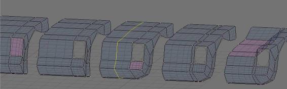
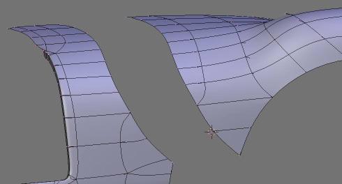
-Pour la découpe
de la partie arrière, il faut faire un cut partiel ("K" et choisir
Knife exact") et utiliser la subdivision pour la partie basse. Une retouche
du maillage sera nécessaire, ainsi que des déplacements de
vertex. Pour faire un déplacement de vertex après subdivision,
mettre le curseur sur un vertex voisin et faire un scale. Il sera nécessaire
de rajouter un vertex en bas de chaque partie pour éviter un arrondi
trop prononcé (voir image 08). |
-In order to cut out the
le backpart of the car, we need to make a partial cut [K key, chosse "Knife
exact"] and use the subdivision for the lower part. Mesh tweaking and vertice
moving are mandatory here in order to get a good result. To move a vertex
after a subdivision, just put the cursor on a neighbour vertex and make
a scale. We will need to add a vertex down each part to neutralise the
round effect. (look at image 08). |
(cliquez l'image pour agrandir)
|
Faire ensuite l'extrusion
de la partie commune (0.01 puis 0.1 BU) en bas pour la partie haute et
vers l'intérieur pour la partie latérale. |
Then extrude the common
part [ 0.01 BU and 0.1 BU] downward for the lower part and inward for the
lateral part. |
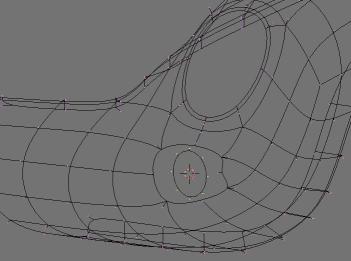
-Faire l'extrusion des passages
de roue avec 0.02 puis 0.4 BU. Idem pour l'habitacle. |
-Extrude parts around tires
of 0.02 BU then 0.4 BU? Do the same for the habitacle. |
-Mettre le curseur sur le
vertex qui est à l'emplacement du clignotant et le supprimer. En
vue de face, ajouter un cercle de 8 vertices et lier le maillage . |
-Put the cursor on th vertex
located in the place of the turning signal light. Select it and delete
it. In Front view [Numpad 1], add a circle of 8 vertices and link all vertices. |
(cliquez l'image pour agrandir)
|
| Déplacer le cercle
légèrement vers l'intérieur. |
Slightly move inward the
cercle. |
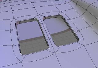
-Pour l'aération
du flat 4, les 2 ouvertures se font par extrusion, après élimination
de 2 edges, puis scaling sur le centre des vertices suivi des 2 extrusions
vers le bas (écarter avant les vertices du milieu pour désarrondir
les coins). |
-For cooling down the flat
4, 2 opening are needed and are made by extrusion, after eliminating 2
edges, then scaling at centre, followed by 2 extrusions downward (It is
best to put some space between middle vertices in order to make the edge
sharper). |
(cliquez l'image pour agrandir)
|
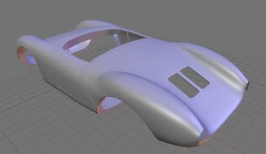
Faire de même pour
les ouvertures à l'avant.
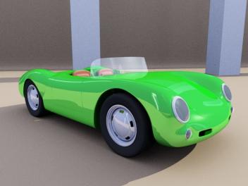
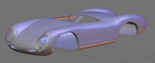
-Finir le modèle est
maintenant assez simple (le pare-brise, le volant, les sièges, les
feux, et les roues) et ne devrait pas poser trop de difficulté si
vous êtes arrivés jusque là. |
Proceed the same way for
the forward opening.
-Finishing the rest is easy
(windshield, steering wheele, seats, lights and tires) and should not cause
much trouble if you manage to survive up to this stage.
|
(cliquez l'image pour agrandir)
(cliquez l'image pour agrandir)
|
-N'hésitez pas à
poser des questions sur :
news://news.zoo-logique.org/3D.Blender |
-Direct all questions to
this newsgroup where we promise to answer in understanble english :
3D.Blender |
@+,
Speedtiti, janvier 2004 |
(Translation JLsB) |